PPS drawing
The Inside of the Galloway Boilers


The six boilers were built by W & J Galloway & Sons.
Patentees & Makers of Manchester.
Boilers No: 1 & 6 where built in 1881 to power the beam engine that
sunk the pilot well, when the water extraction capacity for the
site was proved, the four other boilers (No: 2 to 5) where
ordered and installed in the new pumping station in 1883.
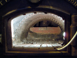
Galloway changed the Lancashire design by using two combustion
chambers or furnaces within each boiler casing, to improve the heat output.
Boilers No 4 & No 6 still have the original Galloway hearths.
Boilers No 1 to No 3 had the hearths replaced by the 'Pillatt'
Perfect Combustion Furnace in the 1920's and boiler No 5
had its hearths replaced at a similar time by hearths from
Wilton Patent Furnace Co. London.
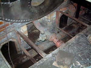
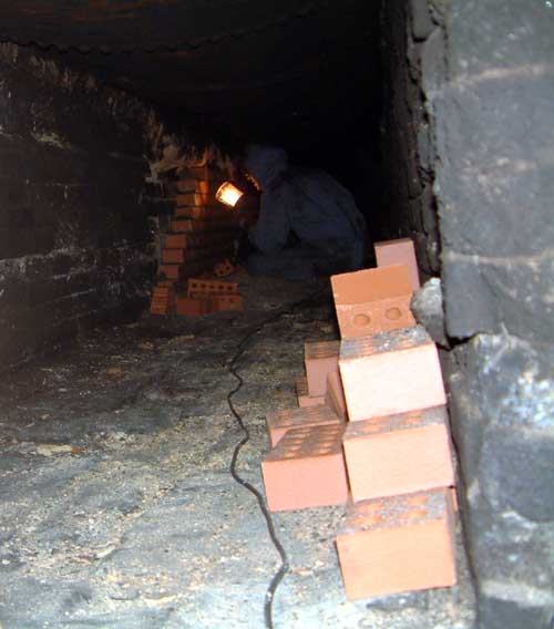
The boilers are 29 ft long and 7 ft in diameter.
The boilers have two furnaces, each of which are 6 ft long by 3 ft wide.
Each boiler holds 3,500 gallons of water and burned 6 tons of coal each day.
This range of boilers are probably the oldest of their type still in use today.

Each boiler produced 8,000 lbs. of steam per hour at a working pressure of 50 lbs.  per sq. in.
Normally 3 of the 6 boilers where in steam at a time to power the two  Beam Engines. The engines pumped 1,500,000 gallons of water per day.

Nowadays only one boiler is in steam on steaming days to power both of engines, as no water is pumped (the well is still connected to live drinking water). The boiler pressure is now 25 - 30 lbs. per sq. in.

Boiler diagram

1.

Boiler Shell

12.

Main Steam Supply to Engines

2.

Furnace Tubes

13.

Combined Low Water Alarm  and Second Safety Valve

3.

Furnace Doors

14.

Boiler Inspection Manhole

4.

Fire Bars

15.

Furnace Damper Mechanism

5.

Bridge & Bridge Plate

16.

Boiler Feed Water Supply

6.

Cross Water Tubes

17.

Boiler Blow Down Valve

7.

Lever Safety Valve

18.

Blow Down Pit

8.

Chemical Dosing Pot

19.

Sole Flue

9.

Return Leg from Engine Cylinder  Jackets Heating Circuit

20.

Side Flue

10.

Main Steam Valve

21.

Main Flue to Chimney

11.

Steam Receiver

22.

Arrows indicating path of  Flue Gases

Six boilers

View of the six 'Galloway Patent' Lancashire boilers

Boiler front Inside top

Boiler No 4 with original Galloway hearths.

A view inside the boiler, over the top of the combustion chamber.
You can see the tops of vertical cross water tubes.
This top part is normally half filled with water, with the upper half, full  of steam from the boiling water, at a pressure of about 25 pounds per square  inch.
The mechanism is the low water level detector and second safety valve.

inside left 

View into two furnace hearths,
this one is being cleaned out.
The wire and hose are being used to vacuum out the soot and ashes,
during the yearly overhaul.

This one shows a usable hearth,
the coal fire sits on the fire grate bars at the bottom of the picture.

Inside bottom

A view under the furnace hearths, the two individual heath tubes join into one tube for the combustion chamber with its vertical water heating tubes passing through the tube from top to bottom of this chamber. In the bottom of the picture is part of the circular outer boiler  shell, this part of the boiler is full of hot water, when is use.

Looking down at the two inspection holes below the boiler, these will normally have sealed covers.
You have to squeeze through these holes for boiler maintenance.

A view under one of the boilers
(item No.22 on diagram above).
One of our members  is replacing the brickwork as part of the ongoing maintenance of these historic  boilers.

3 front 4 front

The left picture shows the "Pillatt Perfect Combustion Furnace" hearth.
The right picture shows the original "Galloway" hearth.

safety valve

One of the dead-weight safety valves on top of the boilers.
The valve lifting pressure was set by the
movement of the weight to the left of the arm.
The further the weight from the valve, the higher the pressure
in the boiler required to release the excess steam.
Nowadays these are set at 30 lb. per square inch.